The truss manipulator is a kind of fully automatic industrial equipment based on the right-angle X, Y, Z three-coordinate system, which can adjust the position of the workpiece or realize the trajectory movement of the workpiece. Its control core is realized by industrial controllers (such as PLC, motion control, single-chip microcomputer, etc.). After the controller analyzes and processes various input (various sensors, buttons, etc.) signals, and after making certain logical judgments, execute commands to each output component (relays, motor drivers, indicator lights, etc.) to complete X, Y , The joint movement between Z three-axis, in order to realize a complete set of fully automatic operation process.
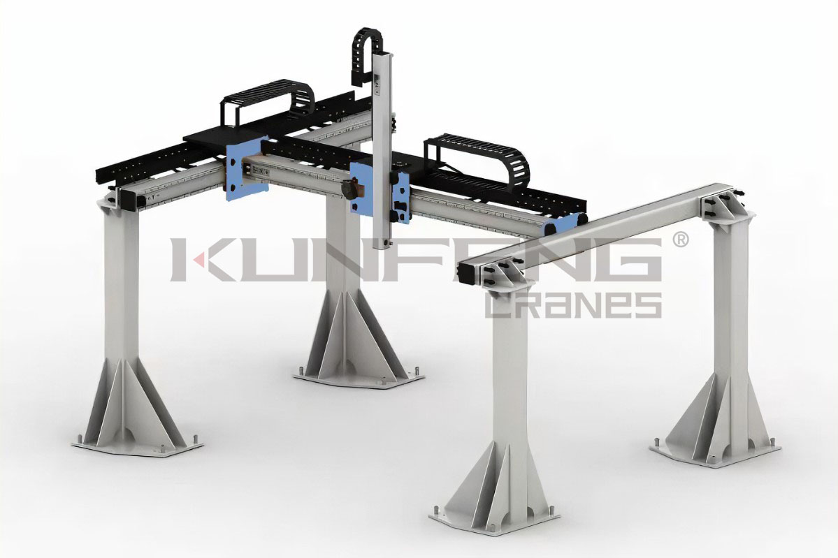
Functional configuration: The manipulator consists of six parts: a structural frame, X-axis components, Y-axis components, Z-axis components, fixtures and control cabinets.
Framework:
It is mainly composed of uprights and other structural parts. Its function is to raise each shaft to a certain height. It is mostly composed of welded parts such as aluminum profiles or square tubes, rectangular tubes, and round tubes.
X-axis components, Y-axis components, Z-axis components:
The three motion components are the core components of the truss manipulator, and their definition rules follow the Cartesian coordinate system.
Each shaft assembly is usually composed of five parts: structural parts, guide parts, transmission parts, sensor detection elements, and mechanical limit components.
1. The structural parts are usually composed of aluminum profiles or square tubes, rectangular tubes, channel steel, I-beams and other structures. Their role is to serve as the installation base of guides, transmission parts and other components, and also the main bearer of the load of the manipulator.
2. Guides, commonly used guide structures such as linear guides, V-shaped roller guides, U-shaped roller guides, square guides, dovetail grooves, etc., and their specific application needs to be determined according to actual working conditions and positioning accuracy.
3. Transmission parts are usually electric, pneumatic, and hydraulic. Among them, electric has a rack and pinion structure, a ball screw structure, a synchronous belt drive, a traditional chain, and a wire rope drive.
4. The sensor detection element usually uses travel switches at both ends as electrical limit. When the moving component moves to the limit switches at both ends, the mechanism needs to be locked to prevent it from overtravel; in addition, there are origin sensors and position feedback. sensor.
5. Mechanical limit group, its function is the rigid limit outside the electric limit stroke, commonly known as dead limit.
Fixture:
There are different forms according to the shape, size, and material of the workpiece, such as vacuum suction, chuck clamping, picking or needle clamp insertion.
Control cabinet:
It is equivalent to the brain function of the truss manipulator. Through the industrial controller, the input signal of each sensor or button is collected to send instructions to each actuator to execute the predetermined action.